Sunday 26 January 2014

Replacing the Mainsheet Horse


Replacing the Mainsheet Horse

The main sheet horse on Tra Bhui when we purchased it showed the normal signs of age that are common on most of the older Drascombes. The galvanized tube had oxidized and had turned a dark grey interspersed with small patches of rust.
The galvanized tube which forms the majority of the horse on the Gig is attached to the gunwales via two stainless steel sockets welded to sections of stainless steel flat bar which in turn are bolted through the gunwale. Where the galvanize steel and the stainless steel meet the rusting was more prominent. Apart from being unsightly I was concerned as to how much steel actually remained at the end of tube. The failure of the horse could be fairly dramatic if it happened in windy conditions.
Removal of the horse is simple as there are two set screws holding each plate on. Remove the crews and the horse and mountings can be gently eased from between the gunwales. I was interested to see how the galvanized steel tube was connected to the sockets. Car body filler was the answer – well epoxy resin and filler, but it is the same stuff. I suppose that this served its function of providing a waterproof seal at each end of the tube and keeping the two different metals apart, but it can hardly be considered cutting edge engineering even by Drascombe standards!
On inspection there was still sufficient metal left to be sure that the strength of the traveler was not compromised. The rusting on the tube however was unsightly so I decided to simply replace the galvanized tube with a bit of stainless steel. Having previously replaced the horse on our Lugger with a stainless steel one I knew how much better it would look.
As the fittings at each end of the horse were already made of stainless steel the easiest option was simply to have a piece of stainless steel tube but welded to them. As I was about to order tubing for the tent that I was making for Tra Bhui I added a piece of 30mm stainless steel tube to the order.
As stainless steel welding beyond my capabilities (and my own welding equipment) I asked a local fabricator to weld it for me. Fifteen pounds later and I had a new horse.

Refurbishment of the Mast and Spars


Drascombe Gig

 Refurbishment of the mast and spars


There are a number reasons why the mast and spars on Tra Bhui need a bit of refurbishment.
1.     Damage – through wear and tear there is some minor damage to the spars. While this is not extensive, small issues such as the split in the boom for the mizzen sail if not repaired in time will eventually lead to rig failure.

2.     Standing Rigging – this was in a very poor state when we purchased Tra Bhui. Before we sailed her for the first time we replaced the standing rigging (the standing rigging is only applicable to the main mast) with a full new set of shrouds and forestay – ex Churchouse Boats.

3.     The placement of the fittings – mainly cleats – are not where I would like them to be e.g. the cleat for the main halyard is at the bottom of the mast which means that to raise the sail you have to be either on your knees or bent double where upon you struggle to see what the sail itself is doing. The jib halyard is cleated on the front of the mast, but the jib cleat is placed where the too close to the thwart making it awkward to use. 

The fittings may reflect Tra Bhui’s previous life as an outdoor education boat when it carried a number of pupils as crew. If crew numbers were not a consideration, I am sure the positioning of the fittings would make more sense, but as we sail as a couple mainly (with limited lone sailing) the fittings need to be moved and or replaced.

4.     The fittings themselves are a bit of a mix match of different fittings of indeterminate age. While most are fine there are certain ones that I am not happy with. As they will all be coming off when the mast is sanded and will be replaced in potentially different positions, I will use this opportunity to replace any worn fittings.

5.     The mast and spars while in good condition have been treated  over the years with a preserver and stain. While this generally looks OK, I hope the actual finish can be improved on.

6.     Mast Head fittings – As the new VHF antenna and mast head light have to be fitted, a route for the associated cabling will have to be set into the mast.


Pole


Drascombe Gig

Pole

Due to its long and virtually un rockered keel Tra Bhui has a great reluctance to turn sharply. While this is absolutely fine when sailing it is a nightmare maneuvering in confined spaces. The size of our outboard along with the minimal opportunity to enlarge the cut out in the transom means that the outboard also wants to keep going in a straight line and subsequently exacerbates the straight line qualities of the keel.
To date we have used our oars to push off the numerous obstacles that have tried to thwart our manoeuvres, however having spent time and effort refurbishing our oars last year I have no wish to see them damaged by their abuse when used in this manner.
The answer is a “pole” or as I advised via the Drascombe Forum a Quant which is what they are seemingly called in the Norfolk Broads. Ideally he pole should be longer than our oars and robust enough to be pushed with but light enough for the “crew” to use. Our oars are approx 10’ long and can be comfortably stored in the cockpit. The pole should ideally be around 15’ long which may necessitate a joint and it being made in two sections.
Ongoing Project  - to be continued

Replacing the Floorboards


New Floor Boards

Prior to our purchase of Tra Bhui the previous owner had fitted new floor boards made of dressed and tanalised pine. While these are perfectly adequate and functional, I would like to replace them at some point with something a bit better looking.
On our previous boat – our Lugger Braveheart – I had made new floor boards out of teak planking which I machined from some large teak beams that I purchased secondhand. For Tra Bhui I wanted to do something a bit different and so I decided that teak gratings was the floor board we would have. I use the term we , but being honest Kathleen was not actually consulted on this and the first she knew of it was when I e-mailed her from Manila to tell her a courier would be delivering 200 No lengths of 40mm x 40mm x 900mm teak sometime that week.
Kathleen to be fair takes these things mostly in her stride and as long as it does not involve me making a mess in the house she lets me potter in my workshop whenever I am home.
The teak was delivered during the summer of 2013 and is stacked and in my workshop where it forms a handy surface to set things down on.
One day I will have time to run the lengths through the thicknesser and start cutting joints, but until then I have a number of more pressing projects to complete on Tra Bhui before the 2014 season starts.

TO BE CONTINUED!!!

Sunday 19 January 2014

Refurbishment of Centerboard Housing and Thwarts


Refurbishment of the Thwarts and Centerboard Housing
During the course of it’s life Tra Bhui has mainly been used for sail training and as such has had considerable fair wear and tear as well as some not so fair wear and tear! Sometime in the past the rear thwart (No 1) had been damaged to the extent that part of the teak had been replaced with a bit of soft wood spliced in and painted in wood stain. This as you can imagine looks pretty scruffy to say the least!
The rear section of the centerboard housing had also been modified and was capped in decking timber again stained in an attempt to match the rest of the wood trim.
Old cap made of Decking Timber

 
To bring Tra Bhui back up to a decent standard, I wanted to replace the damaged thwart and the decking cladding on the center board housing. I also wanted to mount a compass, a depth sounder and incorporate a fixed VHF radio and electrical witch panel into the whole assembly without creating a monstrous structure which was out of keeping with the boat or which looked like an after fit.
Center Board Housing stripped of timber
Thwarts
First things first – the thwarts and wooden trim around the center board was easily removed as all the bits were fixed in place with brass wood screws or stainless steel bolts. When removing No 1 thwart I also removed the cam cleats for the jib / genoa as these were mounted on to it.
The damaged thwart was set aside – the teak will be put to good use later and the soft wood relegated to the bin.


Old Thwart after sanding 1st of 5 coats of oil being applied


The remaining thwarts and center board capping were sanded to remove the grey weathering and expose fresh wood. Five coats of oil were applied with each coat being lightly sanded once dry prior to the next one being applied.
To replace the damaged thwart a new one was cut from iroko as the cost of teak unless found second hand is prohibitively expensive. While I have some teak beams which I have been ripping and sizing for other projects unfortunately I have nothing wide enough to make a thwart from.
Hopefully the iroko will quickly mellow when exposed to the air and it will provide a near match to the teak over the course of time.
Centerboard housing
To make sure everything fitted into the refurbished housing, I decided that I would build a mock up first. Rather than use sacrificial timber, I decided to use the Iroko that I would use for the final item, however everything would be assembled dry and with as few fixings as possible until I was satisfied that everything worked and fitted OK. 

Mock up of new housing
Of particular concern was the mounting of the compass and whether it would be affected by the centerboard and the nearby VHF radio depth sounder and switch panel. Until everything was dry assembled and the radio powered up I would be unable to measure any compass deviation. If any compass deviation proved too be excessive then I would be able to carry out some reworking without too much problem.
To replace the decking used to cap the centerboard casing from the 1st thwart back towards the helm I cut similar sized pieces from new Iroko. These were then scribed to replicate the curves in the glass fiber molding which formed the centerboard housing.
To accommodate the compass I needed to create a wooden mount approx 200mm wide. This being roughly the same width as the existing short centerboard cap which runs between the 1st and 2nd thwarts it made sense to extend this to the rear of the center board casing and return it on to the cockpit floor. The new wider cap would be supported by the new Iroko fitted on either side in lieu of the recently removed decking timber. 
Using a cardboard template which I had previously cut to suit the compass, a suitable sized and shaped hole was cut in the new cap and the compass mounted.
The radio was set into the center board housing just under the cap on the starboard side. This would allow it to be easily accessed by either myself or the crew when we were sailing. I chose the starboard side as this would allow me to use it with my right hand and steer with my left. By mounting it as high as possible I was able to enlarge an existing rebate in the top of the glass fiber molding of the centerboard which allowed the depth of cavity required for the radio to be achieved.
The depth sounder was also set into the capping and the switch panel into the side of the housing with all the necessary wiring concealed under the capping.

Refurbishment of the Gunwales

Refurbishment of the Gunwales


Before


After


New Tent


Tent
One of the reasons for changing our Lugger Braveheart for a Gig was to gain more living space on board when we were staying away overnight. On Braveheart our tent was simply the flysheet from an old ridge tent, which when hung between the masts provided us with a three sided shelter. As the flysheet did not really match the shape of the hull or the relief of the deck it could only provide us with limited protection from the weather.
On Tra Bhui, we used the tent at rallies on Loch Lomond in September 2013 and on the Norfolk Broads in October 2013. The Loch Lomond Rally was particularly wet but we managed to stay dry as Tra Bhui was pointing into the wind and we both have Gortex outer bags for our sleeping bags. It was however not luxury camping! The tent being open at one end is not ideal for use in marinas or when tied up alongside as there is no privacy at all. For 2014 we were going to have something better.

Having spoken to others and looked at home made and professionally made tents held up by everything from plastic water pipe to drain rods I was quite clear what I wanted for our tent.
1.     The framework must be rigid and capable of standing on its own without the cover
2.     The framework must be maintenance free and easily assembled
3.     The framework should form a uniform shape over which the tent cover could be easily placed
4.     The cover should be waterproof and wind proof
5.     The rear of the tent should be able to be fully opened to expose a large part of the cockpit so that we could also “live outside” if we wanted
6.     A well sealed door would be required at the front to allow access to the anchor
7.     Windows with internal covers would be required on all sides to allow light in and so we could see what was happening outside.
8.     The cover must be able to be secured to the frames so that it did not flap about
9.     The cover should cover the gunwales and form a good seal to the deck
1.   Through eyes at the sides would be required to allow fenders to be hung when we were alongside other boats or a pontoon
Framework
The 8No rowlock sockets on Tra Bhui would make ideal mounting points for the tent frame. At 12mm diameter these would be too narrow to insert the tent poles into, but all that was needed was a male / female connector that could be added to the foot of each pole.
My ideal material for making the framework would be stainless steel tube. Stainless steel tube comes in two grades 214 and 316. Grade 316 is marine grade.  ¾” or 20mm tube would be just the job. With an internal diameter of 16mm I could easily purchase some solid HDPE rod which I could turn down to make the male / female connectors that would go into both the tube and the rowlock sockets. Due to the span and height of each frame the poles would be required to be made up of two individual poles each of which would be roughly a quarter circle.
The tube was sourced on the internet from Metals 4 U.  http://metals4u.com  A horrible name, but a company that I had used before, had a great web site, was easy to deal with and which could supply the required tubing at a competitive price.
Having measured Tra Bhui across each set of rowlock sockets and knowing the height of the tent I wanted I sent out enquiries to a number of tube bending companies as I wanted the tubing radially bent as opposed to incrementally bent. 
Radially bending is carried out on a machine with three moving rollers. Two rollers are fixed and the third which sits between the fixed pair can be adjusted to bend the tube. The rollers are set to the required radius and the tube is passed through them coming out the other end in a nice uniform curve.
Large radius incremental bending is carried out either on a tool like a conduit bender or a hydraulic pipe bender where the tube is forced around a dolly or on a static tube bender where a hydraulic jack with the correct shape dormer is used to bend the pipe at pre determined points. The curve is therefore made up of a number of individual smaller curves.
While the radial bender gives a nicely formed and uniform radius, the incremental benders rely on a number of exactly equal bends being formed at numerous points along the tube. Done well this will give a nice curve – done not well and the tube will look like a thrupenny bit!
The prices that I received back to have the tube bent radially were greater than the cost of the tube and ran to hundreds of pounds. Mindful of my budget I decided that I would bend the tubes myself using the static bender I had in my workshop. Luckily I had a former for 20mm tube. By marking each pipe and making a jig to ensure that each individual bend was the same hopefully I would end up with a reasonable looking frame. 
Making the Frame
By the time I arrived home at Christmas 2013 the tube and HDPE bar had arrived.
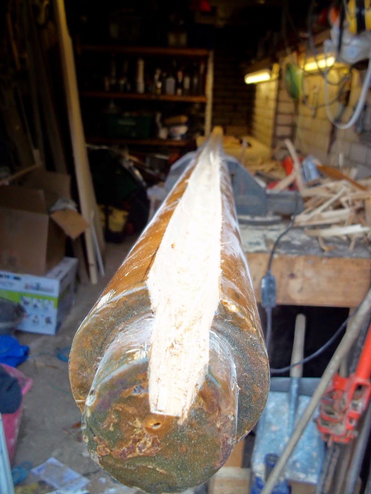
To start the bend off I made up a wooden former from an off cut of 20mm plywood. A number of short strips of ply were screwed to the side to guide the tube as it was being bent. Clamping the former in a vice allowed me to manually bend the tube around the former. As I was cold bending the tube it retained a degree of spring therefore further bending would be required to get it to its final shape.
The next stage in the bending of the tubes involved marking set points along each tube and then making small bends at each point using my tube bender. To make sure each bend was the same I made up a little jig which I could use to measure the distance between the tube and the top of the bender’s frame for each bend. This worked pretty well and soon I had the six quarter circle bends that I needed for the tent all of which looked the same!!
The HDPE rod was then cut into lengths and turned so that one end fitted snuggly inside the tube and the other would fit into the rowlock socket. With the length of HDPE rod inserted, a 5mm hole was then drilled through the tube and an A4 stainless steel bolt passed through to retain the HDPE rod. Stainless steel screws and bolts come generally as grade A2 or grade A4 – Grade A4 is marine grade.
I had originally planned to use HDPE rod to connect the pairs of quarter circle tubes together to form each of the three tent poles. I found however after a few trials that short lengths of 20mm UPVC plastic pipe worked better and made it easier to join the tubes. This would be important as no doubt sometimes we would be erecting the tent in not ideal conditions so simple and easy were the main objectives.
Once I had my three sets of poles they were fitted to Tra Bhui. The shape and outline looked good. I cut two short sections of tube to which I fitted 20mm cupped “T” pieces. These would join the arched tubes together horizontally at the top and give the whole frame some rigidity.

The Cover
My original plan was to make the cover myself, however I realized after thinking about it that the sensible solution was to get someone else to make it up based on a template that I would make. The main drivers behind this were – time, material cost (I would struggle to buy all the bits necessary for the cost of someone else making it up), the lack of a suitable sewing machine and last but not least no experience of sewing things (although this has never stopped me trying things before). 
There are many sail makers /cover makers around the country but I chose to get prices from only a few.
·      R& J Sails (www.rjsails.co.uk) who had just made new jib and mizzen sails for Tra Bhui and who had also made the excellent cover that had just arrived. R& J had previously made the sails for Braveheart and I knew that their product was excellent. 
·      Cover to Cover (www.cover2cover.co.uk) a company who I had not dealt with personally but who came highly recommended and who had a long track record of making similar tents for Drascombes
·      Two local companies who were vague about what they could do and how much it would cost.
In the end I decided to go with Cover to Cover purely based on their history of making Drascombe tents and their budget price being lower than R&J Sails. I must admit to feeling a bit guilty over not using R&J Sails as the quality of their work and service is excellent, however the pictures of the tents that they had made before did not look as good as Cover to Cover’s.
With the frame made but not quite finished I made a pattern for the cover using lightweight polythene. Never having made a pattern before this was a new experience. With the frames marked on the polythene in black marker for reference I added doors, windows, eyelets which would allow our fenders to be hung etc.
The completed pattern was then photographed and removed for posting to Cover to Cover.
The tent will be made up in 150g Acrylic – in a nice bright Dark Grey.
So far I have had a number of conversations with Robert from Cover to Cover and everything so far is going to plan. All going well the tent should be ready in March 2014.

Mock up of front - door and window not shown

Side view of tent front panel

Front view 

Poles marked through on to pattern

Front from inside - material doubled back at the top as a temp fixing


First fit of tent after delivery - note odd bits of string used to hold it in place

Tent trial fit - not too bad looking

Stainless steel hooks fixed to bottom side of rubbing strip 

Tent in use at Broads Rally - Sept 2014

Inside tent - front half as viewed from the stern

Back rolled up - normal daytime living

Lacing Detail